Optics and Accessories Page 4
TO VIEW FULL SIZE IMAGES: USERNAME and PASSWORD are both "mm"
Griffin Armament Fail Safe Angle Sights
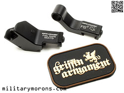
1/16/15 - The Fail Safe Angle Sights from Griffin Armament are designed as a rapid secondary sight system to your primary optic. They're fixed (nothing to deploy), fully adjustable and available in left and right-handed versions. Background - Back-up folding sights are commonly used in conjunction with both magnified and non-magnified optics in case the primary optic fails for some reason. This could be a battery going dead, rendering a red dot or holographic sight useless, or a lens getting damaged or occluded with mud, water, debris etc. Flip-up sights mounted on the top rail in line with the primary optic require the optic to be removed from the rail if it's magnified, or if the lens is damaged or occluded, preventing the user from seeing through the optic to use the sights. The idea behind angled offset sights is to provide a secondary sighting system on the weapon that does not require removal of the primary optic; allowing the shooter to simply rotate the weapon (cant) to utilize them. They can also be used for closer distances when a fixed or variable magnified optic isn't suitable or quick enough. Angled iron sights are not a new concept; they've been used in the 3-gun/competition arena for years. Angled offset sights can be folding, or fixed. Folding sights are lower profile, and less prone to snagging, but require deployment before use. While deployed, a bump against something can fold them partially unless they lock in the deployed position. I know; every option has its set of 'what ifs?' associated with it, some with greater probability than others, but it's not a bad thing to consider all possibilities when making an informed decision about product choices. Griffin's Fail Safe Angle sights are fixed in the deployed position, always ready to use, and are about as simple to use as they come. Description - The Griffin Armament Fail Safe Angle Sights consist of rail-mounted front and rear sights offset at an angle to the vertical plane of the rifle. The front sight features a fully shielded, non-adjustable sight post which provides a HK diopter-style sight picture. The rear sight has a fully-adjustable aperture with which the shooter makes all windage and elevation adjustments without having to use tools (except a coin or cartridge rim/base). The rear aperture is protected on either side by blades. The sights have the same cheek weld as standard sights, requiring the shooter to rotate/cant the rifle inward to make use of them. The Fail Safe sight housings are machined from 6061 T6 and type III hardcoat mil-sped anodized, while the internal parts are 17-4 PH stainless steel. The sights are available in right and left hand versions (left hand shown here). Front sight - The front sight has a fully hooded fixed sight post, and functions like a HK diopter sight. The front sight post does not change in relationship to the hood, so that the circle of the front hood can be used as a quick aiming reference when centered in the rear aperture. With fully hooded front sights that are adjustable for elevation, the front sight post is not always centered in the circle, so that centering the target in the circle isn't always the correct sight picture. With the hood enclosing the sight, you get a clean front sight picture with little chance of glare from sunlight. Except for the markings, the left and right hand versions of the front sight are identical/reversible. The front sight has a Picatinny rail clamp with a single screw, and has 'lobed' geometry so that it's out of the field of view of military IR lasers that are mounted to the top rail. Rear sight - The rear sight aperture is protected on the sides by ears, or blades. The rear aperture is fully adjustable for elevation and windage; eliminating the need to adjust elevation at the front sight. The rear sight housing is made from 6061 T6, and houses the adjustment mechanisms. The rear housing utilizes the same rail clamp as the front sight. The aperture rotates to adjust elevation, and moves up and down in a small block. No tool is needed; you just grab it with your fingers and rotate it 180° where it 'clicks' into a detent. The aperture and block slides left and right on a windage adjustment screw in the sight housing for windage adjustment. There's a flush-mounted slot adjustment on the outside of the housing that can be turned with any flat object like a coin or cartridge case rim. The rear units are left or right-specific, so that lefties didn't have to run the rear sight backwards (although that would be entirely possible to do).
|
Installation and Operation - Installation is simple; just put some thread locker on the screws, place the front and rear sights at the desired location on the top rail, and snug down. Shown here is the left-hand version of the Angle Sights, so they extend to the left of the rifle. The sight picture is almost identical to that of the HK diopter sights; the front sight is centered in the front circle. The rear aperture is sized between the large combat aperture and the small 300 meter aperture, as Griffin wanted to strike a good balance between the two for a single aperture. It's large enough to use for close-up work and precise enough for longer ranges. The sight picture will vary depending on the sight radius used, and how close your eye is to the rear aperture. With a 16.5" sight radius, the rear sight has approximately 60 MOA of windage and elevation adjustment; which should be enough to accommodate any misalignments of upper receiver and handguard rail, or manufacturing tolerance build up. A rifle sight radius would have approximately 54 MOA and a carbine sight radius would have approximately 68 MOA of adjustment range. The Fail Safe sights are shown below in conjunction with a Trijicon TA01NSN ACOG which is a 4x scope. The iron sights on top of the ACOG are for very close range; only the front has any adjustment and the short sight radius leave something to be desired in the accuracy department. However, the 4x TA01NSN can still be used at relatively close range with both eyes open; the fine reticle and magnification just makes it slower to use than an unmagnified red dot. Af ter I had mounted the Fail Safe sights and taken these photos, I swapped them out to another upper that I thought would benefit more from them.
|
 |
 |
This LaRue Stealth upper has a fixed 10x scope on it; and while it has an old Tasco Optima 2000 sight mounted to the scope, the Fail Safe sights were more useful on it than flip-up irons, which required removal of the scope to use. The Optima works relatively well, but they're offset quite a bit and require more of a 'chin weld' than a cheek weld. I installed the Fail Safe sights on the upper, locating the front sight on the rail to give me my preferred sight picture. Moving the front sight forward or backwards on the rail changes its relative size in the rear aperture. I picked a sight radius that allowed me to line up and center the front sight circle in the rear aperture easily when shouldering the weapon, then proceeded to 'bore sight' them in with a laser boresight and double checking them against the Optima red dot.
|
Observations/Notes - At the range, I confirmed my zero at 50 yards (minimal adjustment was needed) by canting the rifle over with the Bobro bipod such that the Fail Safe sights were on 'top' of the rifle. The Bobro bipod actually has more range than the photos below show - I 'rediscovered' it after they were taken. It had been a long time since I used that bipod. Sighting in with the Fail Safe sights was more convenient than sighting in stock factory irons as all the adjustments are done with the rear and you don't have to reach forward in prone and mess with a front sight tool, or get up to adjust the front sight elevation. I find the diopter sight picture (centering circles) easier to use than the standard AR15 sight picture with the bladed front. The Fail Safe Angle sights provide the same cheek weld as the standard sights, which enables the user to transition quickly from the scope to the Fail Safes with a quick inward cant of the rifle without breaking the cheek weld. Canting the rifle does affect the position of the butt pad in the shoulder pocket, but not enough to be an issue. It's a minor adjustment that soon becomes second-nature after shooting with angled sights for a while. The Optima red dot, on the other hand requires me to lift my head up slightly. Obviously, the Fail Safes extend to the side of the rifle, and have a higher profile than fold-down angle sights, but the upside is that they'll likely be there and functional if you need them. The user has to weigh the pros and cons of each setup and determine what works best for him. The offset is also required to ensure that most scope turrets or knobs on the side will not interfere with the line of sight through the Fail Safe Sights. Unless your scope has unusually long and large knobs sticking out to the side, the Fail Safes should be compatible with it. If you're using a magnified optic, and have the need for a secondary sighting system that's immediately usable without removing the primary optic or deploying flip-ups, then angled fixed sights are a solution worth considering. |
Fortis F1 Optics Mount - Lower Third
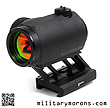
6/25/15 - The Fortis F1 Optic Mount - Lower Third from Fortis Manufacturing is a light weight, low profile mount for the Aimpoint T-1 or H-1 red dot sight. Description - The Fortis F1 Optics Mount is designed for the Aimpoint Micro T-1 or H-1 red dot sights, and is available in a lower third co-witness height model (shown here) and an Absolute Co-witness height model. The one-piece, billet mount is skeletonized to reduce weight; it only weighs 1.1 oz. The top of the mount has the Aimpoint interface to the T-1 or H-1, and the base has a simple Picatinny clamp with two screws that go through two recoil lugs. The top is extended forward to allow the optic to be mounted slightly forward of the flat top receiver. The skeletonized central 'pedestal' has a wider rear column for strength. The F1 is made from 6061-T6 aluminum and Type III Hard Coat anodized. A tiny Fortis logo adorns each side of the base. The F1 is compatible with 3x magnifiers. The F1 does not come with optic screws; the factory screws are used to secure the optic to the F1. The two holes through the base are for mounting screw access for the hex wrench. A vial of blue thread lock is included with the F1 mount, and its use is recommended. Sight picture is like any other lower 1/3 co-witness mount, with the only difference being width (depending on the mount). It's a simple, good-looking, piece for those who don't need a QD mount, and have light weight as a priority.
|
Griffin Armament Micro Modular (M2) Sights
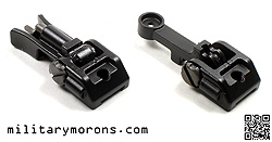
12/21/16 - The Micro Modular (M2) Sights from Griffin Armament are a modular folding back-up iron sight system which can be mounted the standard vertical way, or angled to the left or right depending on the type of base selected. The sights are available as a Sight Deployment Kit which includes both vertical and angled plates, or as separate components. Background - Typically, back-up iron sights are available for either vertical (standard) mounting or angled, but not both. Griffin Armament has come up with a patent pending modular system that utilizes folding front and back sights with interchangeable bases for standard or ambidextrous offset angle mounting. The Sight Deployment Kit is shown here, which includes both vertical and 45-degree mounts. Description - The Micro Modular (M2) sight system is compatible with Picatinny rail systems, and consists of a front and rear sight, and modular bases for vertical and offset angle mounting. This enables the user to switch between vertical and angled configurations without having to buy a whole new dedicated set of sights. The M2 sight system is constructed out of QPQ treated 17-4 stainless and ordnance-grade steel. The sights are amongst the lowest profile on the market. The M2 produces a sight picture similar to the standard M-16; with two blades/ears protecting the sight post. The M2 front and rear sights share the same body/base part. The compact fixed base has a dovetail on the bottom (for attachment to the base plates), and a threaded hole for a set screw that secures it to the rail. The bases are compact and devoid of any sharp edges. There are three scribe marks as a windage reference on the bases, which only applies to the rear sight. The flip-up sights are retained in the up or down positions by stiff spring-loaded detents. A small Griffin Arms logo is laser etched on the side of each body. Front sight - The front M2 sight shares the same body as the M2 rear but the 'windage screw' does not move the front sight to the left or right; it's just there for it to pivot on when folding. A standard front A2 sight post is used, which is nice because the user can swap it out for a thinner post, or tritium post if desired. The post threads down into the body of the sight, and is retained by a spring detent located at the front of the sight. Pressing the detent plunger down disengages the tip from the sight post's notch, and the sight post is free to rotate. An arrow showing the direction of rotation to move the point of impact up is visible from the rear right below the sight post. Rear sight - The rear M2 sight has the same body as the front sight, with the same dovetail on the bottom. A slotted windage screw has four spring-loaded detent positions which provide adjustment 'clicks'. The flip-up rear post has a single hooded aperture. The aperture size is .096" (based on my measurement). For reference, a standard rear A2 rear sight has .070" and .200" apertures. The rear sight is not adjustable for elevation; all elevation adjustments are made with the front sight. Windage adjustments can be made with the base of a cartridge. There's a corresponding line in the center of the rear sight that is used for reference with the scribe lines on the sight base.
|
Modular bases - The M2 17-4 stainless steel bases are available separately, or as part of a kit - Griffin offers both. The bases slide onto a Picatinny rail; they do not clamp on, and come with the necessary hardware (set screws). Their cross section shape reminds me of the Tron Recognizer (from the movie - yes, I'm a sci-fi movie geek). The vertical base has a single through-hole at the top, through which the securing set screw passes. The dovetail mates with the bottom of the front and rear sights, which slide onto the base. The 45 degree plate bases are ambidextrous and can be mounted to the top rail off to the left or right. They are secured to the rail with two set screws. The sight mounting plates extend off at a 45-degree angle, and have the 'tail' portion of the dovetail. The sights slide onto the tail and are then secured to the plate with a single set screw. There are three different lengths of set screws. Installation - The angled plates attach to the top rail with two set screws. The set screws supplied with the sights have flat points and no burrs or sharp edges, to minimize marring to the rails. However, they WILL mark the rails. If that's an issue, then you can simply cut a piece of thin material that fits in the groove on the rail to protect it. I cut strips of .010" thick stainless steel shim stock and placed them under the plates for the set screws to bear against. Blue threadlocker is recommended on all fasteners when installing the M2 sights.
|
 |
 |
 |
The vertical plates install the same was as the angled ones by sliding onto the rails, but have a through hole instead of a threaded hole. When the front of rear sight is slid onto the dovetail of the vertical base, the longest set screw is used in the center of the sight base and is tightened so that it engages the top of the rail.
|
 |
Observations/Notes - Like Griffin's other products, the M2 sights are well made, finished and presented. The M2 sights are very compact; smaller than Troy back up iron sights and more similar in size to the KAC Micro or Magpul MBUS Pro sights. It makes you wonder why older BUIS sets needed to be so bulky. They're very low profile; right at about 0.5" above the rail when folded down so the rear will fit under most optics. The lack of Picatinny clamp means that there is less chance of interference with flashlights mounted at 10:30 or 1:30. The lack of a large windage adjustment knob on the rear sight also makes for a more compact package and nothing to get in the way when using the right side of an ambidextrous charging handle. Some may be averse to the set screw method of securing the sights to the rails because they mar the rails, but that's easily remedied (as shown above) with a small piece of shim if you're concerned with cosmetics. Once tightened down, everything feels solid. The spring tension that holds the sights stowed or up in the deployed position is strong; and the detents very positive. I'd have liked to see some serrations or grooves on the outside of the front sight ears to make them easier to grab a hold of when deploying the sight as they're smooth, and require a firm pinch to deploy. The sights deploy and stow with a satisfying 'snap'. There's no wiggle or looseness in either position. Sight adjustment is simple; the rear sight screw uses any small flat item like a screwdriver, coin or 5.56mm case rim to adjust. Front sight elevation adjustment is performed with a standard A2 front sight tool. However, I was actually able to adjust the front sight without any tools by depressing the detent plunger down with my thumbnail nail, and rotating the front sight post with my fingers. The sight picture with the .096" aperture works well; it's not as large as the ghost ring on the A2 but larger than the small aperture. It's a good balance between speed and precision if you only have one aperture to use. Priced very competitively, the M2 sights offer a versatile all-in-one package that guarrantees that they won't end up in the spare parts box. |
TangoDown iO Cover (iO-003) for Aimpoint T-1
8/11/17 - TangoDown Inc has released a revised version of their popular iO Cover for the Aimpoint Micro Series of optics (T-1/H-1/R-1). It maintains the same sleek and snug fit of the original iO cover, but offers improved protection for the optics lens and body. Background - The TangoDown iO cover was introduced in late 2012/early 2013 and has proven to be a very popular add-on for the Aimpoint Micro (T-1/H-1/R-1) series of optics. The project started out as a Kickstarter Project by Joe Chen; then production was then taken up by TangoDown. Read the background in my original article here. Description - The iO Cover builds the lens caps into a protective optic cover for the Aimpoint Micro. It's made of a durable thermoplastic polyurethane material that resists solvents, oils and UV exposure. It can be painted or hydrodipped. The main body of the protective cover acts as a base to attach lens caps with flexible hinges. The front of the Micro optic has a lip for the front lens cap to grab onto in the closed position. The rear lens cap has nothing on the rear of the optic that can be used to keep the lens cap closed. The rear of the iO cover's body extends to the rear just enough to form a ridged lip that the lens cap can snap onto. The front lens cap nests inside the rear cap when stowed on the left side of the optic. The body of the iO Cover has cutouts which expose the battery housing/brightness adjustment knob, and the elevation/windage adjustment caps. The brightness adjustment knob's numbers are covered, except for the top one, which indicates the level of brightness that the optic is set at. When the Aimpoint T-2 was released, it featured lens caps and knob protection integral to the body. The iO-003 version incorporates simlar raised protection for the top adjustment cap into the body for us T-1 users. Here's a summary of differences between the original and -003 iO covers:
Installation and Operation - Installation is simple. The iO Cover is slipped over the front lens first, and worked/stretched over the optic, with the rear ring going around the rear lens last. It's removed by reversing the sequence. It's designed to work with one hand (left or right) using gross movements, even when wearing gloves. There’s nothing small to fiddle with. Just press the lens caps on. Swipe them open using the big tabs and snap them together to stow them to the side. Twist/pop them apart. Observations/Notes - If you liked the original iO cover; you'll be even happier with the improved, -003 version. The rear cap is more positively retained on the new version, and I appreciate the added lens and knob protection. It's a winner.
|
Forward Control Design ATA (Adjustable Turret Cap, Aimpoint Micro)
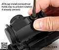
2/11/19 - Forward Controls Design (FCD) has introduced their ATA (Adjustable Turret Cap, Aimpoint Micro), which are replacement turret caps that don't require removal to make elevation and windage adjustments. Forward Controls Design was started in 2014 by former Battle Arms Development partner Roger Wang, to create a better user-centric, form fitting and logical suite of AR-15 and SCAR components with ergonomics as one of the main design goals. Seemingly small changes to common weapon controls, such as the direction of serrations or a slight change in shape can make large differences in the way they feel and how the user interacts with his firearm. Background - The Aimpoint Micro series is one of the most popular mini red dot sights out there at the time of this writing, but have somewhat fiddly caps and adjustments. One of the gripes with the Aimpoint Micro series is that sight adjustments require a proprietary tool to fit into the two holes on top of each adjustment turret so they can be turned. A tool is supplied with each sight, and I keep it in my 'sight adjustment tool pouch' in my range bag. The OEM turret caps have two protrusions so they can be used to adjust the turrents. They're small and fiddly, even for someone like me with small hands. While I haven't lost a cap yet; I've dropped them numerous times. Prompted by a customer request, Forward Control Design decided to come up with their own replacement turret caps which don't require removal to make sight adjustments. Description - The ATA consists of a disc and cap, both machined from 17-4 SS billet and QPQ treated. The disc has two pins on its underside, which correspond to the two holes on the sight adjustment dial. There is a slot on the top of the disc and markings to indicate the direction of windage or elevation adjustment. The slot allows the use of a screwdriver, small coin, or the rim of a case (.223, .308, .45 ACP, 9mm etc) to turn the disc and make adjustments. Two caps and discs come in the ATA package; one of the discs is engraved 'UP', and is the elevation disc; the other is engraved 'R', and is the windage disc. The caps and disc can be purchased either in the black QPQ finish or polished stainless. The 16 serrations around the outside of the cap correspond to 16 clicks per 360-degree rotation of the dial. While the cap is not meant to be rotated during adjustment, the serrations can be marked along with the groove in the disc. Water resistance with the ATA installed is on par with the factory cap, as long as both O-rings are retained. Each cap has a pre-installed O-ring, which engages the top of the disc, providing resistance to moisture. The OEM O-ring around the base of the turret is retained, and seals the bottom of the cap to the sight. Installation and Operation - Installation is simple. After t he OEM caps are removed, one of the discs is placed on the adjustment dial, ensuring that the pins are in the holes, and the cap is installed and screwed down. If your optic is already zero'd and you don't want to disturb it, use a screwdriver to prevent rotation of the disc when screwing the cap down. As the internal O-ring inside the cap compressed against the dial, the dial can rotate with the cap. If you're installing the ATA on an optic that hasn't been zero'd you don't have to worry about the disc rotating. That's why it's important to have the O-ring lubricated with silicone-based lubricant. The O-ring inside the cap is pre-lubricated; and an additional pair of lubricated O-rings are included in the package. When first installed, the cap is just tightened down until both the internal O-ring and O-ring at the bottom of the turret are compressed and the cap is snug; not mashed down. The dial should be able to be adjusted without the cap rotating. Some rotation of the cap is allowed (about 90-degrees in either direction) while adjusting the dial, but you can always hold on to it while rotating the dial. Observations/Notes - Manufacturing quality and design of the ATA are top notch; which is what I've come to expect from FCD. FCD has made a name for themselves by focusing on the details and making smaller incremental inprovements. When combined together on a complete rifle, the improvements (in my opinion) add up to more than the sum of their parts. So, who is the ATA really designed for? The idea behind the OEM cap design is 'set it and forget it'; which I'd reckon works for most users. I have had more need to adjust zeros because I tend to swap out optics from upper to upper (for reviews etc), and have had to re-zero more often than someone who leaves the optic on the firearm. Using the OEM caps to adjust the dials works, but isn't the easiest even under perfect conditions as they're so small. The supplied adjustment tool works better, as long as you have it with you. Do it in the field, and there are more chances to lose the caps once they're off. The ATA is designed for those who don't want to remove caps or use a special tool to adjust the dials. Adjusting the dials with the ATA is also much faster as there's nothing to remove, and simpler since it can be done with anything that fits in the slot - coins, case rims, screwdriver bit etc. One thing I wondered about what whetehr the clicks would be less distinct due to the drag/pressure that the O-ring compression puts on the dials. No worry there; the clicks were still distinct and audible. The question about whether bumping can cause the cap to rotate and move the dial with it arises. It's really difficult to rotate the cap with a bump; it really requires holding both sides and twisting. Even if the cap is bumped, the dial should remain stationary as long as the O-ring is lubricated. I've pictured my T-1 with TangoDown -003 iO cover, which I highly recommend, as it has additional protection for the elevation caps/adjustment knob. The ATA cap does extend above the iO cover protectors, as well as those on the T2, but partial protection is better than none at all. Whether you need/want the ATA or don't; you can be assured that it's a well thought-out and designed accessory.
|
ATTENTION! PLEASE DO NOT LINK DIRECTLY TO MY IMAGES
-
IT RESULTS IN MY BANDWIDTH ALLOCATIONS BEING EXCEEDED,
AND MY PAGES GO DOWN. THANKS!
/ . PLEASE
OBSERVE AND RESPECT OUR COPYRIGHT! . /
©opyright by MilitaryMorons.com. All Rights Reserved. Reproduction, Duplication,
Distribution Strictly Prohibited.
Unless mentioned otherwise, content and images are the
property of militarymorons.com and are not in the public domain.
They are not to be used without
permission. Please Contact
me for permission to use any images or content herein.
